Optics Teaching Guide
Conceptual Foundations
Law of Reflection
- The incident ray, the reflected ray and the normal lie in the same plane
- The incident ray and the reflected ray lie on opposite sides of the normal
- (angle of incidence = angle of reflection)
Law of Refraction (Snell's Law)
Light from an optically rarer → a denser medium: the angle of refraction < the angle of incidence (it bends toward the normal).
Total Internal Reflection
Condition: and , where .
Thin-Lens Imaging
| Object distance | Nature of the image | Application |
|---|---|---|
| Inverted, diminished real image | Camera | |
| Inverted, magnified real image | Projector | |
| Upright, magnified virtual image | Magnifying glass |
Using the Builder
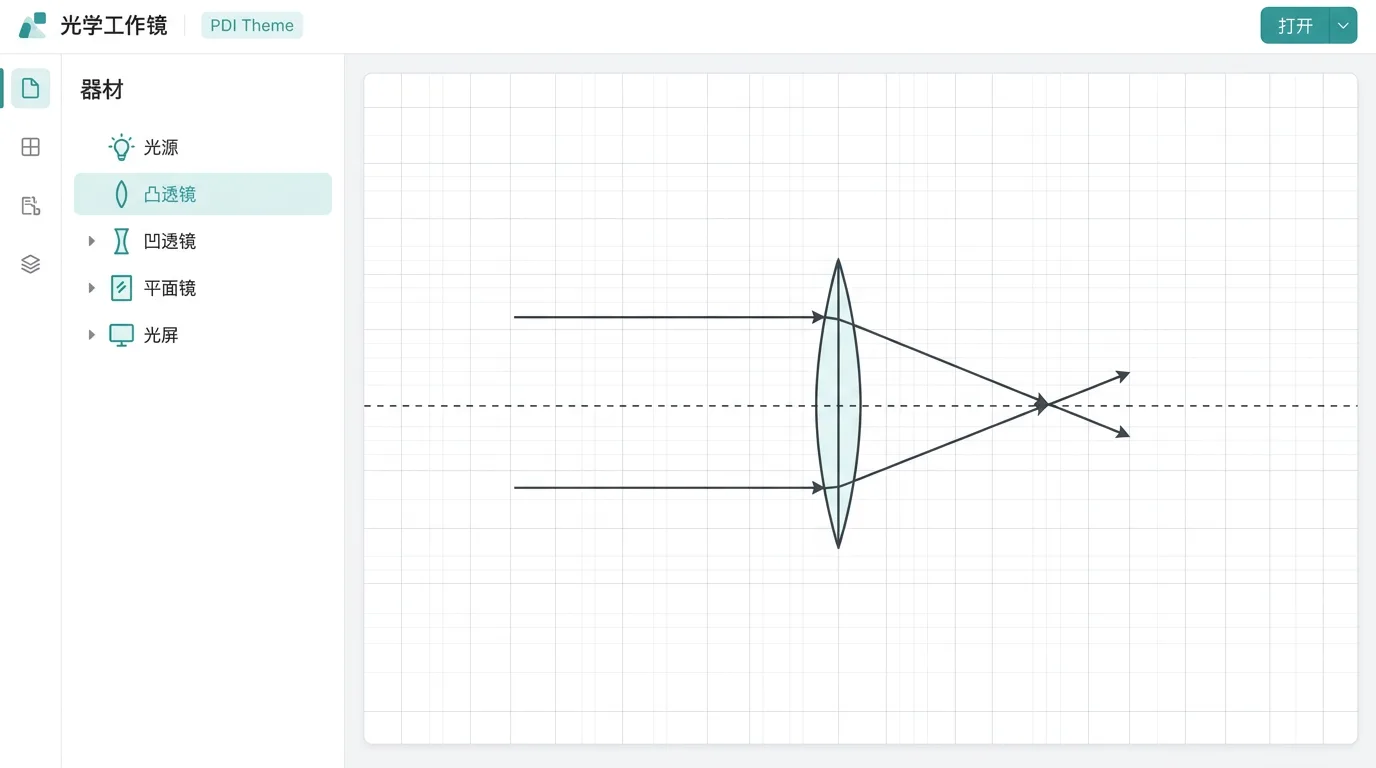
Open the optics builder (nav bar → Builder → Optics). The canvas is a 2D optical bench, about 12 m wide and 7 m tall. Click an entry in the component library on the left to add it, drag it on the canvas to place it, and change its parameters on the right. Rays leave the light source and bend automatically at medium interfaces according to the laws of reflection and refraction.
Gestures
| Operation | How |
|---|---|
| Select a component | Single-click the component on the canvas (its property card opens on the right) |
| Move a component | Press and drag |
| Rotate / set focal length | After selecting, drag the round handle next to the component (plane mirror/lens/source) |
| Quick parameter edit | Double-click a component to pop up its parameter box in place |
| Delete a component | Select it and press Delete, or use the "Delete" button on the property card |
| Zoom the canvas | Mouse wheel |
| Draw a free-form medium | Drag vertices to reshape / double-click an edge to add a point / Alt+click to delete a point |
A one-line gesture hint always sits in the top bar; glance at it whenever an operation slips your mind.
Detailed Component Reference
Light Sources
Single ray (ray)
A point source that emits a single ray - the most basic light source.
| Parameter | Symbol | Unit | Range | Default | Notes |
|---|---|---|---|---|---|
| Position x | x | m | −6–6 | −3.5 | Source position |
| Position y | y | m | −3.5–3.5 | 0.8 | — |
| Rotation angle | angle | ° | −180–180 | −15 | Direction the ray leaves (0° = to the right, counterclockwise positive) |
Used for: studying the reflection/refraction path of a single ray and measuring angles.
Demo idea: pair it with a plane mirror to verify , and with a glass slab to verify the law of refraction.
Parallel beam (beam)
Several equally spaced parallel rays, simulating sunlight or a collimated laser beam.
| Parameter | Symbol | Unit | Range | Default | Notes |
|---|---|---|---|---|---|
| Position x | x | m | −6–6 | −3.5 | — |
| Position y | y | m | −3.5–3.5 | 0 | Beam centre |
| Rotation angle | angle | ° | −180–180 | 0 | Direction of propagation (0° = to the right, counterclockwise positive) |
| Width | width | m | 0.1–3 | 0.8 | Total beam width |
| Number of rays | count | — | 2–15 | 5 | How many parallel lines |
Used for: lens focusing (parallel light through the focus) and prism dispersion.
Fan beam (fan)
A fan-shaped diverging beam emitted from a single point.
| Parameter | Symbol | Unit | Range | Default | Notes |
|---|---|---|---|---|---|
| Position x | x | m | −6–6 | −3.5 | Divergence centre |
| Position y | y | m | −3.5–3.5 | 0 | — |
| Rotation angle | angle | ° | −180–180 | 0 | Central direction of the fan |
| Spread angle | spread | ° | 5–120 | 40 | Angle the fan opens through |
| Number of rays | count | — | 2–15 | 7 | — |
Used for: simulating a point source shining on a lens or mirror to observe imaging.
Refracting Media
Glass slab (slab)
A rectangular transparent block of medium.
| Parameter | Symbol | Unit | Range | Default | Notes |
|---|---|---|---|---|---|
| Position x | x | m | −6–6 | 0 | Centre position |
| Position y | y | m | −3.5–3.5 | 0 | — |
| Width | width | m | 0.3–8 | 2.4 | Horizontal size |
| Height | height | m | 0.2–4 | 1 | Vertical size |
| Rotation angle | angle | ° | −180–180 | 0 | Overall rotation (0° = placed upright, counterclockwise positive) |
| Refractive index | n | — | 1.05–1.9 | 1.5 | Ordinary glass 1.5 |
Used for: observing the lateral shift as light passes through a parallel-sided glass slab (the emergent ray is parallel to the incident ray but offset).
Cylindrical glass / water drop (circle)
A circular transparent medium.
| Parameter | Symbol | Unit | Range | Default | Notes |
|---|---|---|---|---|---|
| Position x | x | m | −6–6 | 0 | Centre of the circle |
| Position y | y | m | −3.5–3.5 | 0 | — |
| Radius | radius | m | 0.2–2.5 | 1 | — |
| Refractive index | n | — | 1.05–1.9 | 1.5 | Water drop 1.33 |
Used for: simulating refraction in a water drop (the principle of the rainbow) and a cylindrical lens.
Triangular prism (prism)
A triangular prism, for observing dispersion and deviation.
| Parameter | Symbol | Unit | Range | Default | Notes |
|---|---|---|---|---|---|
| Position x | x | m | −6–6 | 0 | — |
| Position y | y | m | −3.5–3.5 | 0.9 | — |
| Apex angle | apexAngle | ° | 20–100 | 60 | Standard prism 60° |
| Height | height | m | 0.4–2.5 | 1.2 | — |
| Rotation angle | angle | ° | −180–180 | 0 | — |
| Refractive index | n | — | 1.05–1.9 | 1.5 | — |
Used for: white-light dispersion (the refractive index differs by wavelength) and measuring the angle of minimum deviation.
Demo idea: shine a parallel beam on the prism and watch the emergent ray deviate; the larger the apex angle, the greater the deviation.
Semicircular glass block (semicircle)
A semicircular medium with a flat edge and a curved (arc) edge.
| Parameter | Symbol | Unit | Range | Default | Notes |
|---|---|---|---|---|---|
| Position x | x | m | −6–6 | 0 | Centre of the circle |
| Position y | y | m | −3.5–3.5 | 0 | — |
| Radius | radius | m | 0.3–2.5 | 1.1 | — |
| Flat-face direction | flatAngle | ° | −180–180 | 90 | Which way the flat face points: 90° = face down (standard), 0° = face right |
| Refractive index | n | — | 1.05–1.9 | 1.5 | — |
Used for: the classic experiment to measure the refractive index. When light travels from the centre toward the flat edge, it is not refracted at the arc (it runs along the normal) and refracts only once at the flat edge, which simplifies angle measurement.
Demo idea:
- Shine the ray in through the arc (aimed at the centre) → it refracts at the flat edge
- Increase the angle of incidence step by step and watch the angle of refraction grow
- Find the critical angle (angle of refraction = 90°) and verify
Regular polygon glass (polygon)
A regular polygon block of medium.
| Parameter | Symbol | Unit | Range | Default | Notes |
|---|---|---|---|---|---|
| Position x | x | m | −6–6 | 0 | — |
| Position y | y | m | −3.5–3.5 | 0 | — |
| Radius | radius | m | 0.3–2.5 | 1 | Circumradius |
| Number of sides | sides | — | 3–10 | 6 | 3 = triangle, 6 = hexagon |
| Rotation angle | angle | ° | −180–180 | 0 | — |
| Refractive index | n | — | 1.05–1.9 | 1.5 | — |
Water surface · half-plane (water)
A horizontal interface: air above, water (or another medium) below.
| Parameter | Symbol | Unit | Range | Default | Notes |
|---|---|---|---|---|---|
| Water surface height | surfaceY | m | −3–3 | 0 | y-coordinate of the interface |
| Refractive index | n | — | 1.05–1.9 | 1.33 | Water 1.33 |
Used for: objects in water looking shallower than they are (refraction imaging) and total internal reflection seen from underwater.
Custom medium (custom)
A medium region of free-drawn shape. You must draw it with the "Draw a free-form medium" button in the top-left corner (clicking "Custom medium" in the library only adds a shapeless placeholder and shows no light path). Suited to water drops, irregular glass and the like.
| Parameter | Symbol | Unit | Range | Default | Notes |
|---|---|---|---|---|---|
| Position x | x | m | −6–6 | 0 | — |
| Position y | y | m | −3.5–3.5 | 0 | — |
| Refractive index | n | — | 1.05–1.9 | 1.5 | — |
Shared medium options: white-light dispersion and overlap priority
All media (slab, prism, water, custom medium...) have two shared options:
- White-light dispersion (white): when on, this medium refracts according to the crown-glass index table (red 1.513 → violet 1.532), so white light passing through splits into six colours. Note the name clash with the source's "White light (six colors)" - there it means emitting composite white light, here it means the medium splitting it; a dispersion experiment needs both switched on.
- Overlap priority (priority): omitted = 0 for water and 1 for the other media. Where two media overlap, the larger value wins (on a tie, the one added later wins). Water defaults to 0 so that objects immersed in water (glass, air bubbles) automatically override it.
Reflective Elements
Plane mirror (mirror)
| Parameter | Symbol | Unit | Range | Default | Notes |
|---|---|---|---|---|---|
| Position x | x | m | −6–6 | 0 | Centre of the mirror |
| Position y | y | m | −3.5–3.5 | −1.5 | — |
| Length | length | m | 0.4–8 | 3 | Effective length of the mirror |
| Rotation angle | angle | ° | −180–180 | 0 | 0 = vertical mirror |
Used for: verifying the law of reflection and plane-mirror imaging (an upright virtual image the same size).
Spherical mirror · concave/convex (curved_mirror)
| Parameter | Symbol | Unit | Range | Default | Notes |
|---|---|---|---|---|---|
| Position x | x | m | −6–6 | 0 | Vertex of the mirror |
| Position y | y | m | −3.5–3.5 | 0 | — |
| Radius | radius | m | 0.2–10 | 2 | Radius of curvature () |
| Arc-facing direction | angle | ° | −180–180 | 0 | Which way the reflective face points: 0° = right, 90° = up |
| Aperture angle | aperture | ° | 10–170 | 60 | Opening angle of the mirror; larger means a wider mirror |
Note:
- Concave mirror (converging): , parallel light converges to the focus
- Convex mirror (diverging): the radius only accepts positive values (0.2–10); turn the rotation angle by 180° (or point the mirror's opening away from the source) and the reflective face points outward, giving a convex mirror
- The imaging formula is the same as for a thin lens:
Lenses
Thin lens · convex/concave (lens)
| Parameter | Symbol | Unit | Range | Default | Notes |
|---|---|---|---|---|---|
| Position x | x | m | −6–6 | 0 | Centre of the lens |
| Position y | y | m | −3.5–3.5 | 0 | — |
| Focal length | f | m | −5–5 | 1.5 | Positive = convex lens (converging), negative = concave lens (diverging); f=0 is invalid, the engine rejects it |
| Refractive index | n | — | 1.05–1.9 | 1.5 | Coupled with the focal length: the surface radius is derived from f and n as r=2|f|(n−1); changing n does not change the focal length but reshapes the surfaces in step; n=1.0 is invalid |
| Height | height | m | 0.2–4 | 1.6 | Lens aperture (vertical) |
| Thickness | thickness | m | 0.1–1 | 0.3 | Affects the display only |
| Rotation angle | angle | ° | −90–90 | 0 | 0 = placed upright (a lens is left-right symmetric, so ±90° covers every orientation) |
Note:
- : convex lens (converging), parallel light converges to the focus
- : concave lens (diverging), parallel light diverges (the backward extensions pass through the virtual focus)
- f=0 and n=1.0 are invalid: the surface radius r=2|f|(n−1) collapses to 0; the property panel flags it in red on the spot and the engine rejects the submission
- Division of labour between f and n: f sets the optical power (how strongly it converges), n sets the surface shape and dispersion - changing n does not change the focal length, but the surfaces flatten in step
- Rays that fall outside the lens height (aperture) are clipped
Auxiliary Elements
Screen (screen)
A screen that receives rays, used to observe real images.
| Parameter | Symbol | Unit | Range | Default | Notes |
|---|---|---|---|---|---|
| Position x | x | m | −6–6 | 3 | — |
| Position y | y | m | −3.5–3.5 | 0 | — |
| Length | length | m | 0.4–8 | 3 | — |
| Rotation angle | angle | ° | −180–180 | 90 | 90° = vertical screen |
Used for: moving the screen to find the position of a real image (where the rays converge). A virtual image cannot be caught on the screen.
Using the Lab
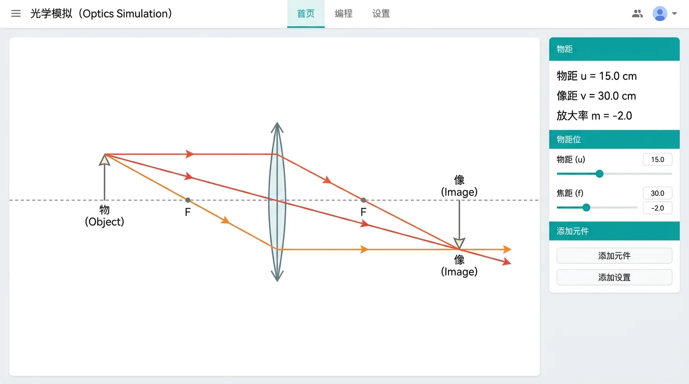
Click "Run it" to enter the lab:
- Light paths computed automatically: incident/reflected/refracted rays are distinguished by colour
- Normals shown: dashed normals at the incidence points
- Angle labels: the angles of incidence, reflection and refraction are labelled with their values
- Extension lines: the backward extensions (virtual-image positions) are shown dashed
- Total internal reflection notice: when the TIR condition is met the refracted ray vanishes and a notice appears
- Parameter scan: change the angle of incidence / refractive index / object distance and watch the angle of refraction / image distance change
Common Problems and Cautions
- A ray disappears: the ray is not aimed at any component. Adjust the source's rotation angle or position.
- No total internal reflection: it must go from an optically denser → a rarer medium (). Light entering glass from air never totally internally reflects.
- You cannot see the virtual image: a virtual image is formed where the extension lines meet; tick "extension lines" to show it.
- Sign of the focal length: convex lens, concave lens, f=0 invalid (the engine rejects it). Setting it wrong makes the imaging entirely wrong.
- Paraxial approximation: rays at large angles deviate from the formula's prediction (spherical aberration); this is normal physics.
- Aperture clipping: rays outside the height range of a lens or mirror are clipped; this is not a bug.
Teaching Suggestions
- Verify the law of reflection: single ray + plane mirror; vary the angle of incidence and record the angle of reflection.
- Measure the refractive index: single ray + semicircular glass block; enter through the arc and measure the angle of refraction at the flat edge.
- Total internal reflection: semicircular glass block; increase the angle of incidence step by step until the refracted ray vanishes.
- Convex-lens imaging: fan beam + convex lens + screen; change the object distance and watch how the image changes.
- Dispersion: parallel beam + triangular prism; observe that different colours deviate by different angles.
Related Experiments
- Verify the law of reflection:
- Investigate the law of refraction:
- Determine the refractive index of glass: pin method / semicircular-block method
- Observe total internal reflection: find the critical angle and compute
- Rules of convex-lens imaging: vary the object distance systematically
- Dispersion of light: splitting light with a prism