Circuit Teaching Guide
Conceptual Foundations
Ohm's Law
Conditions: purely resistive circuits at constant temperature.
Ohm's Law for a Closed Circuit
Series and Parallel
| Connection | Current | Voltage | Equivalent resistance |
|---|---|---|---|
| Series | |||
| Parallel |
Electric Power
RC Charging and Discharging
The process is essentially complete after (99.3%).
Using the Builder
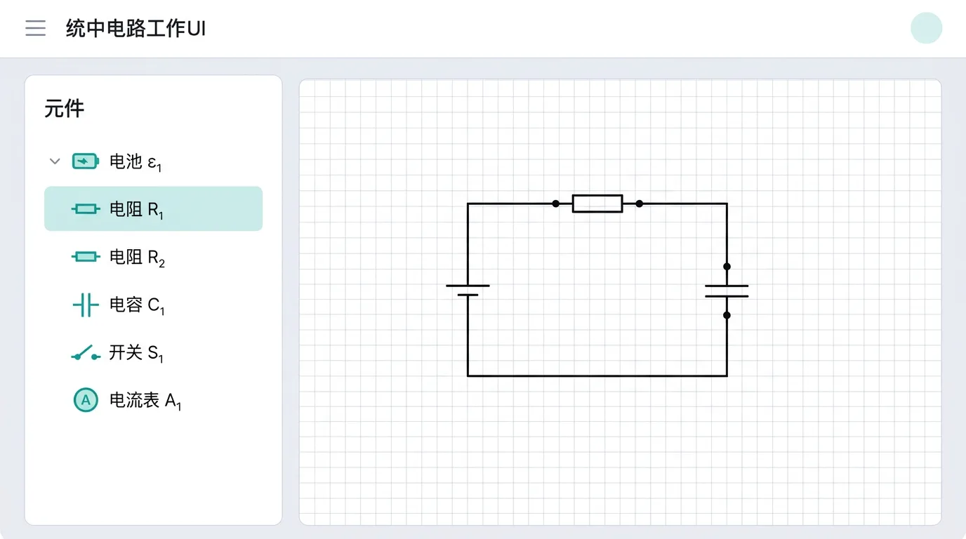
Open the circuit builder (nav bar → Builder → Circuit). Components are placed on the grid canvas: pick one in the component library on the left, then drag out its two terminals on the canvas to place it - terminals landing on the same cell join into one node automatically, with no separate wiring; to change a connection, just drag a component's terminal. The circuit works only once it forms a closed loop containing a source (while it is open, the "Check for issues" panel on the right says so).
Gestures
| Operation | How |
|---|---|
| Place a component | Pick it in the component library → drag two points on the canvas (first press = start terminal, release = end terminal); Esc cancels |
| Select a component | Single click |
| Move a component | Press and drag |
| Quick parameter edit | Double-click a component to pop up its parameter box in place |
| Rewire | Drag a component's terminal (terminals landing on the same cell connect automatically) |
| Move the ground reference | Drag the ground symbol on the canvas |
| Delete a component | Select it and press Delete, or use the "Delete" button on the right |
A one-line gesture hint always sits in the bottom-right corner of the canvas; glance at it whenever an operation slips your mind.
Detailed Component Reference
Power Sources
EMF source (emf_source)
A real source model with an EMF and an internal resistance.
| Parameter | Symbol | Unit | Range | Default | Notes |
|---|---|---|---|---|---|
| EMF ε | emf | V | 0–24 | 6 | Dry cell 1.5 V, accumulator 2 V per cell |
| Internal resistance r | internalResistance | Ω | 0–10 | 0.5 | Small for new cells (~0.1), large for old ones |
Note:
- With it is an ideal source: the terminal voltage always equals
- Short-circuit current - the smaller the internal resistance, the more dangerous a short circuit
- Sources in series: total , total
Constant-current source (current_source)
Delivers a constant current, unaffected by the load.
| Parameter | Symbol | Unit | Range | Default | Notes |
|---|---|---|---|---|---|
| Current | current | A | 0–10 | 1 | Constant output current |
Used for: special analysis problems; rarely seen in practice.
Resistors
Fixed resistor (resistor)
The most basic circuit component.
| Parameter | Symbol | Unit | Range | Default | Notes |
|---|---|---|---|---|---|
| Resistance R | resistance | Ω | 0–1000 | 10 | 0 = compute from geometric parameters |
| Resistivity ρ | resistivity | Ω·m | 0–0.001 | — | Use with L and S via |
| Length L | length | m | 0–10 | — | — |
| Cross-sectional area S | area | m² | 0–0.0001 | — | — |
Note: if resistance is set to 0, the system computes it from (used in the resistance-of-a-wire measurement experiment).
Resistance box (resistance_box)
Integer-step resistance values, emulating a laboratory resistance box.
| Parameter | Symbol | Unit | Range | Default | Notes |
|---|---|---|---|---|---|
| Resistance R | resistance | Ω | 0–9999 | 100 | Integer steps |
Rheostat (rheostat)
A continuously adjustable resistor.
| Parameter | Symbol | Unit | Range | Default | Notes |
|---|---|---|---|---|---|
| Maximum resistance | maxResistance | Ω | 1–300 | 20 | Resistance when fully engaged |
| Wiper position | wiper | — | 0–1 | 0.5 | 0 = far left (least resistance), 1 = far right |
| Rated current | ratedCurrent | A | 0–5 | 0 | 0 = no overload check |
Note:
- The resistance actually in the circuit = maxResistance × wiper
- Exceeding the rated current burns it out (the simulation issues a warning)
- Two hook-ups: current limiting (in series) or potential divider (all three terminals connected)
Thermistor / photoresistor (controlled_resistor)
A resistor whose value is set externally; simulates sensors.
| Parameter | Symbol | Unit | Range | Default | Notes |
|---|---|---|---|---|---|
| Current resistance | resistance | Ω | 1–5000 | 50 | Set manually |
Loads
Lamp (lamp)
A nonlinear load whose brightness changes visibly.
| Parameter | Symbol | Unit | Range | Default | Notes |
|---|---|---|---|---|---|
| Rated power | ratedPower | W | 0.1–100 | 4 | — |
| Rated voltage | ratedVoltage | V | 0.5–36 | 4 | — |
| Filament nonlinearity | nonlinear | — | 0–1 | 0 | 0 = linear (constant R), 1 = resistance rises with temperature |
Note:
- The resistance follows from the ratings:
- With nonlinear=1 the cold resistance is small and the hot resistance large (the I-V curve bends)
- Actual voltage > rated voltage → over-bright / burn-out warning
Motor (motor)
A non-purely-resistive load with back EMF.
| Parameter | Symbol | Unit | Range | Default | Notes |
|---|---|---|---|---|---|
| Back EMF | backEmf | V | 0–24 | 8 | Generated while turning; |
| Winding resistance | windingResistance | Ω | 0–20 | 1 | Heating losses |
Physics: , input power , heating power , mechanical power .
Note: when the motor is stalled, and the current is enormous (stall current).
Energy-Storage Elements
Capacitor (capacitor)
| Parameter | Symbol | Unit | Range | Default | Notes |
|---|---|---|---|---|---|
| Capacitance | capacitance | μF | 1–10000 | 100 | |
| Initial voltage | initialVoltage | V | 0–24 | 0 | Pre-charged voltage (for discharge experiments) |
Note:
- In DC steady state a capacitor is an open circuit ()
- Transient currents appear only in charge/discharge analysis
- With initialVoltage > 0 the capacitor discharges as soon as the circuit is closed
Inductor (inductor)
| Parameter | Symbol | Unit | Range | Default | Notes |
|---|---|---|---|---|---|
| Inductance | inductance | mH | 1–10000 | 100 | |
| Initial current | initialCurrent | A | 0–10 | 0 | Stored current |
Note:
- In DC steady state an inductor is a short circuit ()
- Switching off produces a high voltage (self-induced EMF); the larger , the more pronounced
- Time constant
Measuring Instruments
Ammeter (ammeter)
| Parameter | Symbol | Unit | Range | Default | Notes |
|---|---|---|---|---|---|
| Internal resistance | internalResistance | Ω | 0–10 | 0 | 0 = ideal (no voltage drop) |
| Range | range | A | 0–10 | 0 | 0 = no over-range check |
Note: must be connected in series. With internal resistance = 0 it leaves the circuit undisturbed; with internal resistance > 0 it slightly reduces the current.
Voltmeter (voltmeter)
| Parameter | Symbol | Unit | Range | Default | Notes |
|---|---|---|---|---|---|
| Internal resistance | internalResistance | Ω | 0–100000 | 0 | 0 = ideal (no shunt current) |
| Range | range | V | 0–300 | 0 | 0 = no over-range check |
Note: must be connected in parallel across the component under test. Keeping the default internal resistance of 0 gives an ideal voltmeter (no shunting, no effect on the circuit); only set a finite value (e.g. 3000 Ω) when examining how the voltmeter's own resistance affects the measurement (the "treat the voltmeter as a large resistor" type of problem).
Multimeter (multimeter)
| Parameter | Symbol | Unit | Range | Default | Notes |
|---|---|---|---|---|---|
| Mode | mode | — | 0–2 | 0 | 0 = current, 1 = voltage, 2 = ohm |
| Range | range | — | 0–300 | 0 | A in current mode, V in voltage mode |
Galvanometer / meter movement (galvanometer)
| Parameter | Symbol | Unit | Range | Default | Notes |
|---|---|---|---|---|---|
| Full-scale current | fullScaleCurrent | mA | 0.1–100 | 1 | — |
| Internal resistance Rg | internalResistance | Ω | 1–1000 | 100 | — |
Used for: meter-modification experiments. A small resistor in parallel → converted into an ammeter; a large resistor in series → converted into a voltmeter.
Control Elements
Switch (switch)
| Parameter | Symbol | Unit | Range | Default | Notes |
|---|---|---|---|---|---|
| Closed | closed | — | 0–1 | 1 | 1 = closed (conducting), 0 = open |
Single-pole double-throw switch (spdt_switch)
| Parameter | Symbol | Unit | Range | Default | Notes |
|---|---|---|---|---|---|
| Throw position | position | — | 0–2 | 0 | 0 = throw 1, 1 = throw 2, 2 = open |
Used for: charge/discharge switch-over (throw 1 connects the source to charge, throw 2 connects the resistor to discharge).
Fuse (fuse)
| Parameter | Symbol | Unit | Range | Default | Notes |
|---|---|---|---|---|---|
| Rated current | ratedCurrent | A | 0.1–20 | 2 | Blows above this current |
| Resistance | resistance | Ω | 0–10 | 0 | 0 = ideal wire |
Diode (diode)
| Parameter | Symbol | Unit | Range | Default | Notes |
|---|---|---|---|---|---|
| Forward voltage | forwardVoltage | V | 0–2 | 0 | 0 = ideal diode |
| Real diode | real | — | 0–1 | 0 | 1 = nonlinear I-V characteristic |
Note: conducts forward (anode potential > cathode) and blocks in reverse. Connected backwards, it carries zero current.
Auxiliary Elements
Wire (wire)
No parameters. Joins two terminals; an ideal wire has zero resistance.
Alarm / threshold (alarm)
| Parameter | Symbol | Unit | Range | Default | Notes |
|---|---|---|---|---|---|
| Trigger voltage U₀ | threshold | V | 0.1–24 | 3 | Triggers when the voltage across it exceeds this value |
Using the Lab
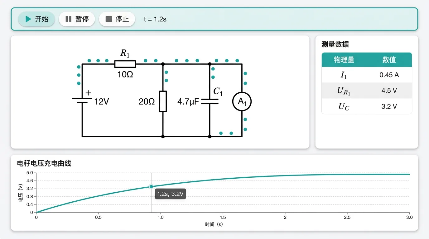
Click "Run it" in the top toolbar to enter the lab (it runs the current canvas directly, no need to save first):
- DC analysis: shows each branch current (arrow + value), every component's voltage and power
- Charge/discharge analysis: plots the - and - curves in real time
- Show potentials: wires are coloured by potential (red = high, blue = low)
- Current animation: moving dots indicate the current direction
- Parameter sweep: vary one component's parameter and watch the current/voltage/power change
Common Problems and Cautions
- The circuit doesn't work: a closed loop is required. Check for unconnected terminals (hollow dots).
- Short circuit: a wire straight between the source's + and − terminals (no load) → enormous current; the simulation issues a red warning.
- Meter hook-up: ammeter in series, voltmeter in parallel. Reversing them changes the circuit or gives wrong readings.
- Capacitor in steady state: in DC analysis the capacitor branch carries zero current (open circuit). To watch the charge/discharge process you must select the Charge/discharge analysis mode.
- Reference direction: a negative current means the actual direction is opposite to the labelled one - not an error.
- Voltmeter internal resistance = 0: this means an ideal voltmeter (the shorthand for infinite internal resistance), not a short circuit.
- Ground reference: the ground symbol (0 V) must touch a component terminal (directly or through a wire) for the reference to sit where you put it; if it floats, the engine automatically takes the negative terminal of the first source as 0 V (the builder's "Check for issues" panel warns you).
Teaching Suggestions
- Verifying Ohm's law: source + fixed resistor + ammeter + voltmeter; vary the source voltage and record the data.
- Measuring EMF and internal resistance: vary the rheostat, record several pairs, plot the - graph.
- RC charging and discharging: source + resistor + capacitor + single-pole double-throw switch; throw 1 charges, throw 2 discharges.
- Modifying a meter: put a resistor in parallel/series with a meter movement and verify the range-extension formulas.
- Motor power: observe the energy split .
Related Experiments
- Verifying Ohm's law: ,
- Measuring resistance with the voltmeter-ammeter method: compare the errors of the internal and external connections
- Measuring a source's EMF and internal resistance: the graph method
- RC charging and discharging: verify the exponential law, measure
- The lamp's I-V characteristic: nonlinear - curve
- Series and parallel circuits: verify the voltage-divider and current-divider rules